Author: Fahad Ambusaidi
Supervisor: Dr. Nasrellah Hassan
Journal of Advanced Structural Engineering and Design 2025
Submission received: 16 July 2025/ Accepted: 21 July 2025/ Published: 23 July 2025
ABSTRACT
This paper carries out an inquiry into how shear wall locations affect the seismic behaviour of multi-storey reinforced concrete (RC) buildings. Four structural layouts of a bare frame (M1), the shear wall at the core (M2), at the external middle (M3), and at the external corners (M4) were modelled and analysed under dynamic seismic loading using STAAD Pro. All the models were exposed to constant material parameters, imposed loads as well as seismic in the form of El Centro earthquake data. To compare the effectiveness of all configurations, key performance measures, which are Story Lateral Displacement, story drift ratio, natural frequency, and time period, were considered. The results indicate that the erection of shear walls at the exterior corners is the most resistant to lateral action giving the minimum lateral displacement and drift, the maximum frequency and stiffness. Based on the study, it has been concluded that shear wall positioning is a compelling aspect of promoting the dynamic stability of buildings during earthquakes.
INTRODUCTION
Background
High-rise residential and commercial building construction has become a part of development to meet the demands of high-rise buildings because of rapid urban population growth especially in the seismically active areas (Sharma and Sain, 2024). With the increase in building heights, increased attention is being paid by the structural engineer to the increased importance of resistances of the building through lateral loads due to wind and earthquakes. Such forces have the ability to generate a significant amount of stress on tall structures, which can cause extreme or even collapse barring proper control. Among the best strategies for increasing lateral load strength is the addition of shear walls, which are vertical design structural pieces that resist horizontal loads. In addition to enhancing the rigidity of the structures, shear walls restrict lateral displacements and inter-storey drift, as well as providing the overall structural integrity (Mustafa et al., 2023). The response of a building to the dynamics loading is also considered using several performance indicators: story drift, maximum lateral displacement, natural frequency, time period
Story drift is the horizontal movement of a story relative to an adjacent level of the building, and when it is large enough, can jeopardise both structural and non-structural elements. The vibration frequency and time interval determine the way the structure reacts to the seismic excitation; a longer time interval indicates that the structure is more compliant and vice versa. To promote the safety and serviceability of buildings to occupants, international building codes (IS 1893, and BS EN 1998) provide a limit to these parameters (Archana and Akbar, 2021). Even though the structural advantages of shear walls are well-known, there still exists a significant lack of knowledge concerning the performance of said walls based on their position within the building. Although certain research has been conducted regarding this, the results are not very comprehensive and universal. This study will focus on bridging this gap by modelling buildings of differing shear wall placements and testing their seismic performance.
Research Aim
The aim of this study is to assess the effect of shear wall location on the seismic response of a multi-storey RCC building.
Research Objectives
The objectives are:
- To model RCC buildings with various shear wall locations using STAAD Pro.
- To compare seismic performance metrics: displacement, drift ratio, frequency, and time period.
Problem Statement
The issue is that there seems to be no unanimity about where to place shear walls. The faulty location may undermine the seismic strength of a structure, result in a poor utilisation of materials and make a building susceptible to seismic activity.
LITERATURE REVIEW
Due to the necessity of good lateral load-resisting systems in buildings of high rise, much research on structural systems like bracing systems, diagrids, outriggers and shear wall systems has been conducted. The article by Hussaini (2020) offers a comparative analysis of bracing systems, diagrid systems, and outrigger mechanisms as the solutions to seismic force resistance in tall buildings. Bracing systems, he claims, are cheap and simple to construct but are inefficient in buildings more than 30 storeys high because of over-flexibility. Conversely, in diagrid systems, the column orientation is changed to diagonal members that turn all of the forces into axial loads. According to Hussaini, it is this that makes diagrids the winner in distributing lateral loads effectively. Nevertheless, his summary does not analyse shear walls closely, especially regarding their location effects beyond the overall discussion on the lateral resistance techniques best practised.
Filling this gap, Yadav and Yadav (2022) tested the performance of shear walls in a G+25 building at two locations, one in the core and the other at the corners of the building. Their results indicate that the corner location of shear walls allows for to reduction of storey drift and lateral displacement by a factor of 10, relative to placing the same shear walls in the core. Outer shear wall strategy also boosted overall structure stiffness. This goes in line with the basic structural vibration principles according to which the stiffer something is the shrinker natural frequencies and the shorter the time period is more desirable in seismic designing (Yang et al., 2023). Bisen et al. (2022) complement this conclusion with an ETABS-simulated comparative analysis of shear wall location placement. They show that structures’ shear walls lead to high displacement and drift.
Their paper moreover indicates that the external location of shear walls particularly at the corners of the building always minimises the base shear and the displacement along with the storey drift. This strengthens the hypothesis that structural walls not near the centre augment the moment arm and consequently the torsional resistance hence having better seismic performance. Nevertheless, the simulated data used in the review by Bisen has not been tested experimentally or in practice and therefore might not be generalisable. Theoretically, the dynamic response of a structure is usually measured in terms of story drift and period of time. story drift ratio (IS 1893:2016 and BS EN 1998-1) such as 0.004 and 0.007 have been proposed, and structural systems that restrict the deformation in the lateral direction are recommended to protect lives and property (Yashwanth and Tamizharasi, 2023). Both Yadav and Bisen’s studies utilised Response Spectrum Analysis (RSA) which is highly recommended because of its capacity to examine the reaction of a building to a ground motion taking modal characteristics and damping impacts into consideration.
Recent works conducted by Kawsarul and Kabbo (2024) go further and state that the most balanced between the walls is a combination of shear walls both core and corners. Their G+13 analysis of several different seismic zones found that such dual placement not only helps in the restraint of lateral shift but also helps to control the basic time period within code-tabled restrictions. Nevertheless, they observe that even such an arrangement fails to meet the requirements in high-seismic areas such as Zone V, implying that the structural systems need well-adjusted adaptation of local seismicity. In sum, these studies show how the location of the shear wall plays a paramount role in the seismic response.
METHODOLOGY
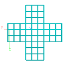
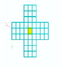
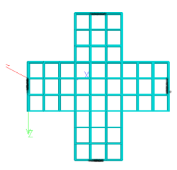
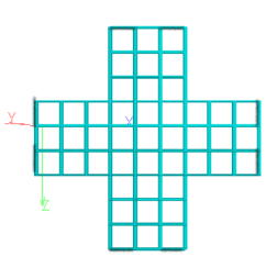
A dynamic analysis of the seismic case on a reinforced concrete (RC) multi-storey building was conducted in the current study using STAAD Pro, a well-established structural analysis and design package. The aim of the modelling was to consider the implication of shear wall position on the response of the building to lateral loads. Four alternative building arrangements were examined to establish the optimum shear wall location. These are; M1, a bare frame, having no shear walls; M2, where shear walls are at the centre core of the building; M3, where the shear walls are at the centre of sides of the building; and M4, where shear walls are at external corners of the building. The same structural layout was used to construct all the models to achieve consistency and allow direct comparison. The architectural planning was of G+7 (eight-storey) plus shape. In the two directions, X and Y each bay was spaced at 4 metres.
Several parameters remained uniform in all models like concrete grade M25 and reinforcement steel grade Fe415. The modulus of elasticity of concrete and steel was standardised as well to facilitate a valid comparison of the material properties used. The lateral forces were based on the ground motion of the El Centro Earthquake (1940) as a reference point; which is commonly used to calculate structural response (Abd-Alameer and Abbas, 2023). The seismic loading was a design loading based on the appropriate international codes with dead loads, live loads, superimposed loads and the seismic input in accordance with the British Standard (BS) code (Hussain, 2024). The four most important dynamic response parameters were used to evaluate performance namely: Story Lateral Displacement; story drift ratio, natural frequency, and fundamental time period. These measurements have been selected on the basis of suggestions in IS 1893 and BS EN 1998-1, which suggest these measurements are significant in assessing structural resilience during earthquakes. With such controlled variables, the expected outcome of the study is to isolate and quantify the effect of shear wall location on seismic behaviour.
Table 1: Materials Properties Of The Building Model
| Materials properties | values |
| Grade of concrete | M25 |
| Grade of steel | Fe 415 |
| Young’s modulus of elasticity for steel (Es) | 200,000 Mpa |
| Modulus of elasticity of concrete (Ec) | 25,000 Mpa |
Table 2: Structural Details
| The shape of the building | Plus, shape |
| No. of bays in X | 10 |
| No. of bays in Y | 10 |
| Spacing X Direction | 4 m |
| Spacing Y Direction | 4m |
| No of floors | G+7 |
| Size of beam | 230mmX600mm |
| Size of column | 450mmX450mm |
| Slab thickness | 150mm |
| Share wall thickness | 230mm |
| Hight of storey | 3.2m |
| Foundation height | 2m |
| Soil type | medium |
Table 3: Load Data
| Imposed load | 3kN/m2 for floor (1.5 KN/m2) for roof slab |
| Superimposed load | 13.156 KN/m |
| Floor finish | 1 KN/m2 |
| Parapet load | 6.072KN/m |
| Seismic load | BS code |
Table 4: Seismic Parameters
| Sz | Structural type | R | Importance Factor |
| iii | SMRF | 5% | 1 |
RESULTS AND DISCUSSION
Maximum Story Displacement
Maximum story displacement is the sideways lateral movement produced by seismic effects on the building at different levels. As illustrated in Tables 5, 6, and Figure 1, the trend shows that as the height of the building increases displacement also tends to rise in effect to form the dynamic behaviour of lateral loading. Model M1, which was the bare frame structure was observed to have the largest displacement at all offices with the highest of the displacement being at the roof level of 16.148 mm at the height of 25.6 m. Contrariwise, the Model M4 that has extended the shear walls to the external corners of the building had the lowest displacement of 13.615 mm at that level. This implies that shear wall location has considerable impacts on the stiffness and lateral stability of the structure. M2 (shear wall at the core) and M3 (shear wall at external middle) also outperformed M1 but suffered under the hands of M4 at every level. This trend establishes the fact that shear walls placed at the perimeter of a building (particularly at the corners) offer maximum moment resistance as caused by the torsional stiffness of the surroundings. Those results were replicated in the works by Bharat et al., (2024), who focused on the usefulness of shear walls located in the corners to reduce lateral sway.
Table 5: Maximum Story Displacement For All Models In Each Floor
| Maximum Story Displacement (Mm) | ||||
| Height (m) | bara frame building | share wall located at the core | share wall located at the eternal
middle |
share wall located at the eternal corner |
| 0 | -4.904 | -2.138 | -2.347 | -2.042 |
| 3.2 | -4.904 | -3.592 | -3.18 | -3.763 |
| 6.4 | -7.312 | -4.953 | -4.167 | -5.575 |
| 9.6 | -9.428 | -6.326 | -5.284 | -7.205 |
| 12.8 | -11 | -7.646 | -6.473 | -8.794 |
| 16 | -12.951 | -8.919 | -7.694 | -10.268 |
| 19.2 | -14.412 | -10.103 | -8.892 | -11.62 |
| 22.4 | -15.512 | -11.161 | -10.04 | -12.769 |
| 25.6 | -16.148 | -12.054 | -11.087 | -13.615 |
| M1 Share Wall Located At Core | |
 |
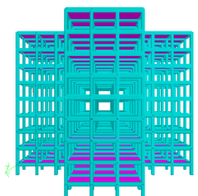 |
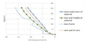
Figure 1: Maximum Story Displacement
Story Drift Ratio
The important parameter in seismic design is the story drift ratio which is the relative lateral displacement between two adjacent stories. Too much drift may lead to structural damage, non-structural damage (e.g. partition cracks and cladding cracks) and collapse. Table 7, Table 8 and Figure 2 demonstrate that Model M1 with no shear walls resulted in the largest drift ratios with a maximum value on the second floor of 0.0008378, which, though below the upper edge of 0.007, which are prescribed in the IS 1893 and BS EN 1998-1, is large compared to other models. The drum frames (model M4) s had once again the lowest drift ratio values of 0.00021 and 0.00037, which were still way below safe and serviceable limits. M2 and M3 similarly had lower drift ratios than M1, but these were less efficient than M4. These findings support the finding that the placement of external shear walls enhances the lateral stiffness of the structure thereby minimising diagonal story drift. Similar to Rusi, (2021), it was also observed that corner shear walls were more effective at controlling story drift compared to core-placed walls, where the premises experienced a seismic loading, as in the case of high-rise buildings.
Table 7: Story Drift Ratio For All Models
| Story Drift Ratio | ||||
| Height (m) | bara frame building | share wall located at the core | share wall located at
external middle |
share wall located at the external corner |
| 0 | 0 | 0 | 0 | 0 |
| 3.2 | 0.000837813 | 0.000454375 | 0.000543 | 0.00021 |
| 6.4 | 0.0007525 | 0.000425313 | 0.000504 | 0.000308 |
| 9.6 | 0.00066125 | 0.000429063 | 0.000509 | 0.000349 |
| 12.8 | 0.000321563 | 0.0004125 | 0.000497 | 0.000371 |
| 16 | 0.00034375 | 0.000397813 | 0.000461 | 0.000382 |
| 19.2 | 0.000456563 | 0.00037 | 0.000423 | 0.000374 |
| 22.4 | 0.000344063 | 0.000330625 | 0.000359 | 0.000359 |
| 25.6 | 0.00019875 | 0.000279063 | 0.000264 | 0.000327 |
Table 8: Layout And Section Of Bara Frame Building With Core At Centre
| M2 Share Wall Located At Core | |
 |
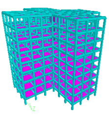 |
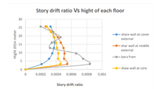
Figure 2: Story Drift Ratio In Each Floor
Frequency
Natural frequency shows the stiffness, as well as, the mass distribution of a structure. The higher the frequency the more it is stiff and resistant to dynamic oscillation. Model M4 has produced the highest frequency values in all three vibrating modes with Mode 1 standing at 1.462Hz, Model 1 was also at 1.021Hz lowly (Table 9, 10 and Figure 3). The models M2 and M3 were in the middle value, with a slight advantage to M2 over M3 since it has a centralised arrangement of walls, and this can promote stiffness along the axis. The frequency values of M4 are much larger and hence this should be of maximum stiffness and therefore not easily shaken due to the seismic excitation. This is consistent with theoretical knowledge that facilities with more rigid lateral resistance systems (i.e., shear walls located at building corners) have higher natural frequencies, and have less tendency to experience excessive sway. The order observed through frequency performance (M4 > M2 > M3 > M1) is also closely related to the displacement and drift outcomes, confirming that the cause-effect relationships are consistent between the performance outcomes across all variables. Khelaifia et al., (2024) and Zhou et al., (2024) also observed frequency improvement where shear walls were appropriately placed to support the structural extremities.
Table 9: Frequency in All Models in All Shapes
| Type Of Models | Frequency (Hz) | ||
| Mode Shape | |||
| 1 | 2 | 3 | |
| bara frame building | 1.021 | 1.05 | 1.069 |
| share wall located at the core | 1.19 | 1.231 | 1.253 |
| share wall located at the external middle | 1.185 | 1.212 | 1.55 |
| share wall located at the external corner | 1.462 | 1.485 | 1.81 |
Table 10: Layout And Section Of Bara Frame Building With Core At External Share Wall At Middle
| M4 Share Wall Located At Eternal Middle | |
 |
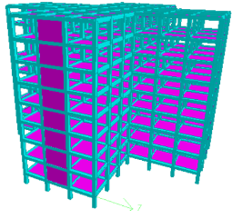 |
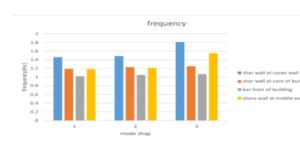
Figure 3: Frequency on each Floor
Time Period
Time period which is the inverse of the frequency is the time it takes a structure to vibrate once. It behaves opposite to structural stiffness, the shorter the time period the stiffer and more stable the building. Table 11, 12 and Figure 4 show that Model M4 Delivered the shortest time periods taking place between 0.552 and 0.684 seconds whereas Model M1 took the longest which was between 0.935 to 0.979 seconds. The core-based (M2) and external-middle (M3) arrangements lay in the middle. These findings indicate that Model M4 is the most sensitive to seismic motion and it is the best in recovering equilibrium the fastest which will limit energy dissipation and structural damages. It can be noted that the performance trend in the time period is also a reflection of frequency as it should be. External corners are modified with shear walls, enhanced lateral stiffness and minimising flexibility, which results directly in realising the monetary time period. This conforms to standards IS 1893:2016 that define less time period as desirable in seismic resilience. A similar pattern in which shear walls were placed outside buildings was associated with less time duration with high seismic loads on tall buildings (Krishnan and Sivakumar, 2023).
Table 11: Time Period In All Models In All Shapes
| Type Of Models | Time Period(S) | ||
| Mode Shape | |||
| 1 | 2 | 3 | |
| bara frame building | 0.979 | 0.952 | 0.935 |
| share wall located at the core | 0.84 | 0.812 | 0.798 |
| share wall located at the eternal middle | 0.844 | 0.825 | 0.645 |
| share wall located at the eternal corner | 0.684 | 0.673 | 0.552 |
Table 12: Layout And Section Of Bara Frame Building With External Share Wall At Corner
| M3 Share Wall Located At External Corner | |
 |
 |
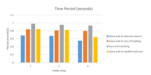
Figure 4: Frequency on each Floor
CONCLUSION AND RECOMMENDATIONS
As has been explained in this paper, the position of shear walls is critical when it comes to identifying the seismic performance of multi-storey RC buildings. By comparing four different configurations, bare frame (M1), core shear wall (M2), external middle shear wall (M3), and external corner shear wall (M4), it was discovered that positioning can have a serious impact on structural response to lateral loading. Out of all tested models, the location of the shear walls in the external corners (M4) provided the best results. This pattern provided the best maximum story displacements and also has the lowest story drift ratios, greatest natural frequencies, and shortest time periods which implies the best stiffness, stability, and seismic excitation resistance.
On the premise of such findings, the exterior corner location of shear walls is advised in medium-rise buildings in seismic regions where lateral load resistance is a key consideration. This method increases safety and structural effectiveness with little to no need to use more material. As a future direction, the research could be extended to compare the performance of different buildings with different heights to see how performance scales with structure size. Also, the effect of irregular shapes like L-shaped or T-shaped floor plans must be considered, especially in combination with openings or asymmetrical distribution of walls. The seismic performance was also assessed on the effects of various soil types and foundations on the performance. Lastly, it would be prudent to use wind load analysis to better understand the structural response to combined later loading conditions.
Acknowledgement
The author would like to express heartfelt gratitude to Dr. Nasrellah Hassan, the project supervisor, for his continuous support, guidance, and valuable insights throughout the course of this research. His expertise and encouragement were instrumental in shaping the direction and quality of this work. Sincere thanks are also extended to the Civil Engineering Department for providing access to essential resources such as STAAD Pro software and laboratory facilities. The author is additionally grateful to all researchers whose previous work laid the groundwork for this study.
Conflict of Interest
The author declares that there is no conflict of interest regarding the publication of this article.
Author Contributions
Fahad Ambusaidi: Conceived and designed the study, conducted the structural analysis, performed the literature review, and prepared the manuscript. All aspects of the research and writing were carried out by the author under the supervision of Dr. Nasrellah Hassan.
References
Abd-Alameer, H.K. and Abbas, H.O., (2023). The Behavior of Braced Excavation in Silty Clay Soil under El-Centro Seismic. Tikrit Journal of Engineering Sciences, 30(4), pp.37-45.
Archana, A.R. and Akbar, M.A., (2021). A critical review of displacement-based criteria for torsional irregularity of buildings. Journal of The Institution of Engineers (India): Series A, 102(4), pp.1169-1175.
Bharat, S.D., Pujari, A.B., Patil, S.K. and Undre, A.R., Impact of Shear Wall Placement on Lateral Load Performance of Building Frames.
Bisen, V., Nirmal, P.K. and Singh, L., (2022). Analysis of a High-Rise Structure Considering Shear Walls of Different Materials with Different Positioning using ETABS A Review. International Journal of Scientific Research in Civil Engineering, 6(1), pp.01-10.
Hussain, N., (2024). Seismic response factors of code-designed high-rise buildings using 3D non-linear analysis (Doctoral dissertation, University of British Columbia).
Hussaini, M. (2020). A Review Paper on Seismic Pareformance of High-Rise Building using Bracing, Diagrid and Outrigger System. International Journal of Engineering Research and, V9(06). doi: https://doi.org/10.17577/ijertv9is060802.
Kawsarul, M.K.I.K.M. and Kabbo, I., (2024). Dynamic Analysis of a G+ 13 Storey Rcc Building Using Shear Wall in Three Different Location on Various Seismic Zone.
Khelaifia, A., Zine, A., Guettala, S. and Chebili, R., (2024). Assessment of the position and quantity of shear walls their correlation with building height on the seismic nonlinear performance. Asian Journal of Civil Engineering, 25(8), pp.5925-5937.
Krishnan, R. and Sivakumar, V.L., (2023). Profound impact of shear wall on stability of regular and irregular reinforced concrete structures–a review. Materials Today: Proceedings.
Mustafa, S.A., Mashaal, M., Shaalan, O. and Khfaga, M., (2023). Shear Walls against Lateral Load s: A Review. The Egyptian International Journal of Engineering Sciences and Technology, 42(1), pp.1-14.
Rusi, I., (2021). Generating Innovative Perforated Patterns for Perimetric Structural Walls with Openings in Multi-Storey Buildings.
Sharma, M.K. and Sain, H.K., (2024). A review on seismic analysis of connected and high rise buildings. International Journal of Engineering Trends and Applications (IJETA), 11(1), pp.18-21.
Yadav, A. and Yadav, P. (2022). Comparative Study of Shear Wall at Two Different Position by Response Spectrum Method. [online] Ijraset.com. Available at: https://www.ijraset.com/research-paper/comparative-study-of-shear-wall-at-two-different-position-by-response-spectrum [Accessed 7 Jul. 2025].
Yang, Z., Yang, H., Tian, T., Deng, D., Hu, M., Ma, J., Gao, D., Zhang, J., Ma, S., Yang, L. and Xu, H., (2023). A review on guided-ultrasonic-wave-based structural health monitoring: From fundamental theory to machine learning techniques. Ultrasonics, 133, p.107014.
Yashwanth, B. and Tamizharasi, G., (2023), December. Code Provisions to Contain Pounding Effects in RC Buildings Under Earthquake Excitation. In Structural Engineering Convention (pp. 233-242). Singapore: Springer Nature Singapore.
Zhou, Y., Chen, Q., Wu, H., Wen, H., Nong, X., Wu, Y. and Xiao, P., (2024). Seismic performance of a frame‐supported shear wall over‐track building through shaking table test. The Structural Design of Tall and Special Buildings, 33(9), p.e2098.